Opto-electronic (optical electronic) components
There are various components that can turn light into electricity or vice-versa. Photocells (also known as photoelectric cells) generate tiny electric currents when light falls on them and they're used as "magic eye" beams in various types of sensing equipment, including some kinds of smoke detector. Light-emitting diodes (LEDs) work in the opposite way, converting small electric currents into light. LEDs are typically used on the instrument panels of stereo equipment. Liquid crystal displays (LCDs), such as those used in flatscreen LCD televisions and laptop computers, are more sophisticated examples of opto-electronics.
There are various components that can turn light into electricity or vice-versa. Photocells (also known as photoelectric cells) generate tiny electric currents when light falls on them and they're used as "magic eye" beams in various types of sensing equipment, including some kinds of smoke detector. Light-emitting diodes (LEDs) work in the opposite way, converting small electric currents into light. LEDs are typically used on the instrument panels of stereo equipment. Liquid crystal displays (LCDs), such as those used in flatscreen LCD televisions and laptop computers, are more sophisticated examples of opto-electronics.
Resistors
The very first component that you should know about is the resistor. It is fairly easy to assume that a resistor, as the name suggests, will resist electricity that flows through it, and you would be correct in that assumption too! Any situation that demands the flow of current to be controlled at a desired level will require a resistor.
Here are two scenarios that better explain what a resistor does. In both cases, we will be turning on a LED:
Scenario 1 – Without Resistor
1. You have power supply on one side.
2. You connect the LED on the other end.
3. The full force of the electricity hits the bulb.
4. This overloads the LED, eventually burning it out completely.
Scenario 2 – With Resistor
1. You have power supply on one side.
2. You connect this to a resistor.
3. The resistor in turn connects to the LED bulb.
4. Electricity flows through the resistor and into the bulb.
5. You can control the amount of electricity that needs to flow to the bulb. As a result, the LED won’t be overloaded and
Capacitors
If a resistor is like a cushion that is used to control the flow of electricity, then capacitors are like small rechargeable batteries that store small amounts of charge in them. Capacitors do two things at the same time:
They allow AC, or Alternating Current, to flow through them.
They resist the flow of DC, or Direct Current, through them.
collection of capacitors
By so doing, they are able to stabilize almost any circuit. There are two types of capacitors that are primarily used:
Polarized capacitors – these have a positive and negative terminal
Non-polarized capacitors – these do not have any positive or negative terminals
@BasicElectronics
Inductors
Inductors are just as complicated as transistors. Just like transistors, inductors are used to build complicated electrical systems. Unlike transistors though, inductors are essentially coils of wire that are wound around other components. They are used as filters.
@BasicElectronics
Inductors are just as complicated as transistors. Just like transistors, inductors are used to build complicated electrical systems. Unlike transistors though, inductors are essentially coils of wire that are wound around other components. They are used as filters.
Of all the electrical components mentioned on this page, you will most likely not use inductors for basic circuit designs. Nonetheless, depending on the particular project that you are working on, inductors just might make an appearance in the circuit’s design.@BasicElectronics
Light Emitting Diode (LED)
I briefly alluded to LEDs in the scenarios that were used under “Resistors” above. LEDs are just like bulbs except that they are extremely reliable. You can find them on practically every appliance in your home that features some kind of an indicator light. A typical LED bulb can last decades with no sign of dying.
@BasicElectronics
I briefly alluded to LEDs in the scenarios that were used under “Resistors” above. LEDs are just like bulbs except that they are extremely reliable. You can find them on practically every appliance in your home that features some kind of an indicator light. A typical LED bulb can last decades with no sign of dying.
Since they are so reliable, they are used to indicate the state of current at any point in a circuit. An important task like checking the output voltage or current on a circuit becomes simpler with these light-based indicators.@BasicElectronics
Transistors
The resistors, capacitors, and LEDs are the simple stuff in electrical circuits. Now, let us talk about the first complicated component – the transistor. Transistors are used to build complex electrical systems, such as amplifiers for instance. A simple way to understand transistors is to think of a switch. A basic switch has an “on” and an “off” state. These are controlled by the position of the switch, which is changed manually.
@BasicElectronics
The resistors, capacitors, and LEDs are the simple stuff in electrical circuits. Now, let us talk about the first complicated component – the transistor. Transistors are used to build complex electrical systems, such as amplifiers for instance. A simple way to understand transistors is to think of a switch. A basic switch has an “on” and an “off” state. These are controlled by the position of the switch, which is changed manually.
A transistor is a more advanced switch that has multiple output states. Unlike a switch, you cannot change these states manually. The only way to switch the transistor between various states is to run current through it. By controlling the current that flows through the transistor, you can control the output state to achieve the results you desire.@BasicElectronics
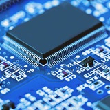
Integrated Circuit (IC)
Integrated circuits are electrical components that combine, or integrate, numerous electrical components, including the ones that were previously mentioned. One IC can act like a transistor while another IC can act like a resistor.
@BasicElectronics
Integrated circuits are electrical components that combine, or integrate, numerous electrical components, including the ones that were previously mentioned. One IC can act like a transistor while another IC can act like a resistor.
An IC is like a ready-made chip that you can use to complete the project you want to build without having to use lots of single transistors or capacitors. As you upgrade from using basic components to integrated circuits, you will find that it is almost always easier to use ICs for your entire project than using individual components.@BasicElectronics
Oscillator:
An oscillator is basically a signal generator that produces a sinusoidal or non-sinusoidal signal of some particular frequency. Oscillators find their various applications as these are the fundamental component of any electrical and electronic circuits.
@BasicElectronics
An oscillator is basically a signal generator that produces a sinusoidal or non-sinusoidal signal of some particular frequency. Oscillators find their various applications as these are the fundamental component of any electrical and electronic circuits.
@BasicElectronics
Ammeter
The meter uses for measuring the current is known as the ammeter. The current is the flow of electrons whose unit is ampere. Hence the instrument which measures the flows of current in ampere is known as ampere meter or ammeter.
The ideal ammeter has zero internal resistance. But practically the ammeter has small internal resistance. The measuring range of the ammeter depends on the value of resistance.
The capital alphabet A represents the ammeter in the circuit.
By the current, the ammeter categorises into two types.
AC ammeter
DC ammeter
@BasicElectronics
What exactly is Ohm's Law?
Ohm's Law describes the way current flows through a material when different levels of voltage are applied. Some materials like electrical wires present little resistance to the current flow and this type of material is called a conductor. Hence if this conductor is placed directly across a battery for example, a lot of current would flow.
The Ohm's Law formula or equation is very straightforward.
Ohm's law can be expressed in a mathematical form:
V=IR
Where:
V = voltage expressed in Volts
I = current expressed in Amps
R = resistance expressed in Ohms
@BasicElectronics
Ohm's Law describes the way current flows through a material when different levels of voltage are applied. Some materials like electrical wires present little resistance to the current flow and this type of material is called a conductor. Hence if this conductor is placed directly across a battery for example, a lot of current would flow.
Ohm looked at the way current flowed in various materials and he was able to develop his law which we now call Ohm's Law.Ohm's Law formula
The Ohm's Law formula or equation is very straightforward.
Ohm's law can be expressed in a mathematical form:
V=IR
Where:
V = voltage expressed in Volts
I = current expressed in Amps
R = resistance expressed in Ohms
@BasicElectronics
Variable Resistor (Potentiometer)
A variable resistor is also known as a potentiometer. These components can be found in devices such as a light dimmer or volume control for a radio. When you turn the shaft of a potentiometer the resistance changes in the circuit.
@BasicElectronics
A variable resistor is also known as a potentiometer. These components can be found in devices such as a light dimmer or volume control for a radio. When you turn the shaft of a potentiometer the resistance changes in the circuit.
@BasicElectronics
Relay
A relay is an electrically operated switch that opens or closes when power is applied. Inside a relay is an electromagnet which controls a mechanical switch.
@BasicElectronics
A relay is an electrically operated switch that opens or closes when power is applied. Inside a relay is an electromagnet which controls a mechanical switch.
@BasicElectronics
What Is A Circuit?
An electronic circuit is a circular path of conductors by which electric current can flow. A closed circuit is like a circle because it starts and ends at the same point forming a complete loop. Furthermore, a closed circuit allows electricity to flow from the (+) power to the (-) ground uninterrupted.
In contrast, if there is any break in the flow of electricity, this is known as an open circuit. As shown below, a switch in a circuit can cause it to be open or closed depending on it’s position.
@BasicElectronics
Electrical filter:
They are :
Active filters and passive filters.
@BasicElectronics
It is a circuit designed to reject all unwanted frequency components of an electrical signal and allows only desired frequencies. In simple it is a circuit which allows only a certain band of frequencies.Applications :
Audio equalizers and in sensitive electronic devices whose input signals should be conditional.These are mainly categorized into 2 types.
They are :
Active filters and passive filters.
@BasicElectronics
What is a volt: unit of voltage
The basic unit of voltage is the volt, named after the Italian scientist, Alessandro Volta, who made some early batteries and performed many other experiments with electricity.
The standard unit of voltage or potential difference and electromotive force in the International System of Units(SI), is formally defined to be the difference of electric potential between two points of a conductor carrying a constant current of one ampere, when the power dissipated between these points is equal to one watt.
@BasicElectronics
Potential difference
The electrical potential or voltage is a measure of the electrical pressure available to force the current around a circuit. A useful comparison for these purposes is a simple system containing water such as a water tank with a pipe attached and the water passing through a half open tap. The higher the level of water above the tap, the greater the pressure forcing the water through the pipe and through the half open tap. The greater the water pressure, then the more water that will flow through the system for a given level of resistance in the system.
@BasicElectronics